Screw Types and Their Measurement Relevance
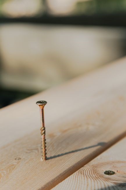
Wood screws feature coarse threads and a tapered shank for wood penetration. Metal (machine) screws have fine‚ uniform threads and a straight shank for precision fastening. Drywall screws possess a bugle head and sharp point to reduce tearing in gypsum. They are selected based on load‚ material‚ environment.!!
Wood Screws

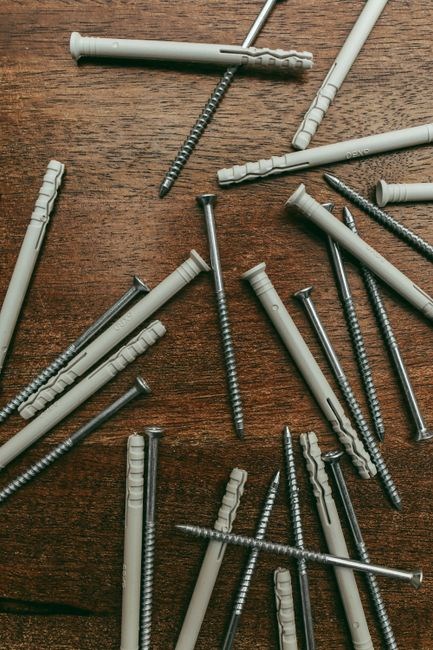
Wood screws are engineered for timber fastening‚ featuring a coarse‚ self‑tapping thread that grips hardwoods and softwoods alike. The shank diameter is typically expressed in gauge numbers (e.g.‚ #6‚ #8‚ #10) or metric equivalents (4 mm‚ 5 mm‚ 6 mm). Length is measured from the tip to the underside of the head‚ ensuring the screw penetrates the required depth without protruding. Head styles vary: flat‚ round‚ pan‚ or bugle‚ each suited to different finish requirements. The thread pitch‚ often 10–12 threads per inch for #6 and #8‚ determines how quickly the screw advances. A larger pitch offers faster penetration but less holding power‚ while a finer pitch provides stronger grip at the cost of speed. For precision work‚ a caliper or digital thread gauge can verify the exact thread diameter and pitch. Wood screws also come in different core materials—steel‚ stainless‚ or brass—chosen based on corrosion resistance and load demands. When selecting a screw‚ consider the wood species‚ moisture content‚ and intended load; a properly sized screw reduces splitting and ensures long‑term stability. In addition‚ the screw’s head type influences the joint’s appearance; a flat head provides a flush surface‚ while a pan head offers a low profile that can be countersunk for a neat finish. When installing‚ always pre‑drill a pilot hole slightly smaller than the screw’s shank diameter to prevent wood splitting‚ especially in hardwoods. Use a torque wrench to avoid over‑tightening‚ which can strip threads or damage the material. Proper screw selection and correct installation technique ensure durable‚ long‑lasting joints in any woodworking project. —
Metal (Machine) Screws
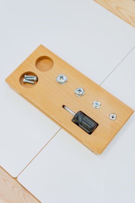
Machine screws are precision fasteners designed for metal-to-metal or metal-to-plastic assemblies. They feature a uniform‚ fine thread along the entire shank‚ with a pitch typically expressed in threads per inch (TPI) or millimetres per thread. Common sizes include #6‑0.25″ (6 mm) with 20 TPI‚ #8‑0.32″ (8 mm) with 18 TPI‚ and metric 4 mm‚ 5 mm‚ 6 mm with 0.5 mm‚ 0.5 mm‚ and 0.5 mm pitches respectively. The shank diameter is measured from thread root to root‚ and the overall length is from tip to the underside of the head. Head styles—hex‚ socket‚ button‚ or pan—are chosen for torque requirements and space constraints. Material choices span carbon steel‚ stainless steel‚ alloy steel‚ and brass‚ each offering specific strength‚ corrosion resistance‚ and electrical conductivity. Thread engagement depth is critical; a minimum of 1.5 times the pitch is recommended to ensure adequate load transfer. Machine screws are often paired with nuts‚ washers‚ or tapped holes‚ and their dimensions must match the mating component’s thread pitch and diameter. Accurate measurement is achieved with a digital caliper or thread gauge‚ and the screw’s tolerance class (e.g.‚ 6g‚ 6g‚ 6g) indicates permissible deviations. In high‑precision aerospace or automotive systems‚ a chrome finish can improve fatigue life‚ while Acme threads provide better load distribution under vibration!
Drywall Screws
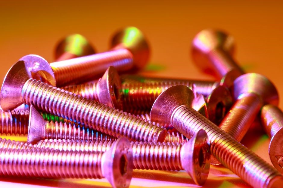
Drywall screws are engineered for gypsum board‚ featuring a bugle head and a sharp‚ tapered point that reduces tearing. Standard lengths range from 1‑½″ to 3‑½″‚ with common sizes 1‑½″ (38 mm) and 2‑½″ (63 mm). The shank diameter is 0.1875″ (4.75 mm) for 1‑½″ and 0.2188″ (5.56 mm) for 2‑½″‚ measured at the thread root. Thread pitch is fine‚ 20 TPI for 1‑½″ and 18 TPI for 2‑½″‚ ensuring a snug fit in pre‑drilled holes. Head width is 0.375″ (9.53 mm) for 1‑½″ and 0.4375″ (11.11 mm) for 2‑½″‚ providing a stable anchor. Length is measured from tip to the underside of the head; overall length must include board thickness plus a ¼″ to ½″ embedment for optimal holding. Materials include cold‑rolled steel for cost‑effective builds and stainless steel for moisture‑prone environments. A 1‑½″ screw weighs 0.25 oz (7;1 g); a 2‑½″ weighs 0.45 oz (12.7 g). Measurement is performed with a digital caliper or screw gauge; tolerance class 6g indicates permissible deviation. Drive types are Phillips or slotted‚ with 1‑inch drive for 1‑½″ and 1‑½‑inch drive for 2‑½″‚ allowing a 1‑¾″ torque. Head depth is 0.25″ for 1‑½″ and 0.375″ for 2‑½″‚ ensuring flush or slightly recessed seating. Pitch diameter is 0.156″ (4 mm) for 1‑½″ and 0.1875″ (5 mm) for 2‑½″‚ providing secure thread engagement. Recommended torque is 1;5 lb‑in for 1‑½″ and 2.5 lb‑in for 2‑½″‚ achievable with a standard screwdriver or power drill. These screws are the standard choice for interior wall and ceiling assemblies‚ delivering reliable holding power while minimizing board damage. They are commonly used in residential construction and commercial drywall installations‚ and provide excellent load distribution.
Key Measurement Parameters
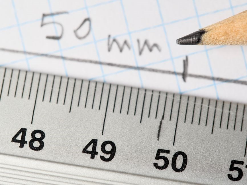
Key measurement parameters include shank diameter‚ thread count‚ overall length‚ and head dimensions. These metrics determine fit‚ load capacity‚ and installation method. Accurate sizing ensures proper torque‚ material compatibility‚ and structural integrity across applications. Ensuring proper fit and load.
Shank Diameter (Gauge Number)
In screw terminology‚ the shank diameter is the core measurement that defines the screw’s strength and compatibility with the material it will fasten; For wood screws‚ the gauge number—ranging from #0 to #10—corresponds to a specific shank diameter‚ with larger gauge numbers indicating thicker shanks. A #0 wood screw typically has a 0.190‑inch (4.83‑mm) shank‚ while a #10 screw measures about 0.190‑inch but with a different thread pitch. Metal (machine) screws use a standardized metric system where the shank diameter is expressed in millimeters‚ such as M4‚ M5‚ or M6‚ each with a precise thread pitch and major diameter. Drywall screws often employ a 1/4‑inch shank for 3/8‑inch heads‚ balancing strength and ease of installation. Accurate measurement of the shank diameter is critical for selecting the correct drill bit size‚ ensuring proper torque‚ and preventing material damage. A caliper or micrometer is the most reliable tool for measuring the shank‚ as it captures the true major diameter across the threaded portion. When converting between gauge and metric‚ reference charts show that a #6 wood screw (0.138‑inch shank) approximates an M3.5 screw (3.5‑mm diameter). Understanding these relationships allows installers to match screws to fasteners‚ anchors‚ and holes‚ guaranteeing structural integrity and longevity in construction‚ woodworking‚ and metal fabrication projects. By aligning the shank diameter with the joint’s load capacity‚ installers can predict performance‚ avoid over‑tightening‚ and ensure long‑term reliability. and precise torque control.!!?This precision is esntial
Thread Count (Threads per Inch)
Thread count‚ expressed as threads per inch (TPI)‚ is a fundamental parameter that determines how tightly a screw engages with its substrate. A higher TPI yields a finer thread‚ which is ideal for metal and precision assemblies where smooth torque transfer and minimal material distortion are required. Conversely‚ a lower TPI produces a coarser thread that offers greater bite and is typically employed in wood and drywall applications to maximize holding power in softer substrates. Wood screws commonly range from 10 TPI for #0–#4 sizes to 16 TPI for #6–#10 sizes‚ providing a balance between penetration depth and shear strength. Metal (machine) screws often use standard metric pitches such as 0.8 mm‚ 1.0 mm‚ or 1.25 mm‚ corresponding to 12.5‚ 10‚ and 8 TPI respectively when converted to imperial units. Drywall screws usually adopt a 10 TPI profile‚ which offers sufficient grip in gypsum board while minimizing the risk of cracking. Accurate measurement of TPI can be performed with a thread gauge or by counting threads over a known length with a caliper. Understanding the appropriate TPI for a given application ensures optimal load distribution‚ reduces wear on fasteners‚ and enhances the overall durability of the joint. Proper selection of thread count is therefore essential for achieving reliable performance across diverse construction and manufacturing contexts. By mastering thread count‚ craftsmen can precisely match screw and material‚ ensuring optimal torque‚ minimizing wear‚ and extending the life of assemblies across woodworking‚ metalwork‚ and drywall projects today now.
Overall Length (Tip to Head)
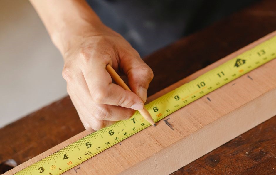
Overall length‚ measured from the tip of the screw to the top of the head‚ is a critical dimension that influences penetration depth‚ clamping force‚ and compatibility with material thickness. For wood screws‚ the length is typically chosen to provide a minimum of 1.5 to 2 times the thickness of the wood to ensure a secure joint. Metal (machine) screws require precise length selection to match the thickness of the mating parts and to avoid over‑penetration that could compromise structural integrity. Drywall screws are often shorter‚ with lengths ranging from 1.5 to 2 inches‚ to accommodate the thin gypsum board while preventing the screw from protruding into the wall cavity. Accurate length measurement can be performed with a ruler or caliper‚ and many manufacturers provide standardized length charts that correlate screw size with recommended application thickness. Selecting the correct overall length is essential for achieving optimal load distribution‚ preventing material damage‚ and ensuring long‑term durability in construction and fabrication projects. By understanding how overall length interacts with material properties and joint design‚ professionals can make informed decisions that enhance performance and safety in every fastening scenario. When measuring overall length‚ it is important to account for the screw head type‚ as countersunk heads reduce the effective length compared to flat heads. For example‚ a flat head screw of 1.25 inches may have a tip‑to‑head measurement of 1.25 inches‚ whereas a countersunk head of the same nominal length may have a tip‑to‑head measurement slightly less due to the head recess. Proper overall length selection also affects the screw’s ability to resist pull‑out forces; longer screws distribute load over a greater area‚ reducing stress concentration at the thread root. In summary‚ overall length is a pivotal metric that must be carefully matched to material thickness‚ head type‚ and application demands to achieve reliable fastening performance. This precision ensures that the screw’s engagement depth aligns with the design’s load‑bearing expectations and maintains structural integrity for performance.
Head Size and Shape
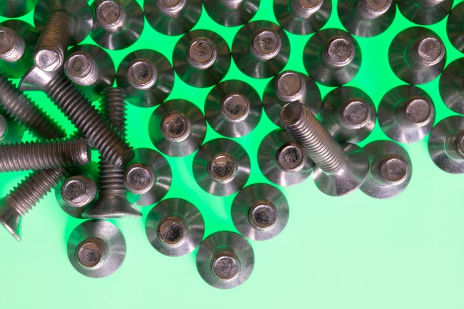
Head size and shape directly influence a screw’s load distribution‚ torque application‚ and aesthetic integration. Common head styles include flat‚ pan‚ round‚ button‚ and hex‚ each offering distinct advantages. Flat heads provide a flush surface ideal for wood or drywall‚ reducing surface damage and allowing countersinking. Pan heads offer a slightly raised profile‚ balancing strength and appearance. Round heads are often used in decorative or structural applications where a smooth contour is desired. Button heads‚ with their low profile‚ minimize protrusion and are favored in automotive or appliance assemblies. Hex heads deliver high torque capability‚ making them suitable for machine screws that require frequent tightening or loosening. The head’s diameter must be proportionate to the shank; a larger head relative to shank can increase shear resistance but may also raise the risk of head cracking under high loads. Material composition—steel‚ brass‚ or stainless—affects hardness and corrosion resistance‚ influencing head durability. Thread engagement depth also depends on head shape; countersunk heads reduce thread engagement‚ whereas flat or pan heads allow full thread contact. When selecting a screw‚ engineers must consider the application’s mechanical demands‚ environmental exposure‚ and finish requirements. Accurate head sizing ensures proper alignment with countersinks‚ prevents head distortion‚ and maintains the structural integrity of the joint. Standardized head dimensions‚ as outlined in ASTM and ISO specifications‚ provide a reference for matching screw heads to mounting surfaces and ensuring compliance with industry safety and performance standards. In addition‚ the head’s material finish—such as zinc plating‚ chrome‚ or black oxide—affects both corrosion resistance and compatibility with surrounding components!!!
Tools‚ Conversion‚ and Reference Resources
Calipers measure thread diameter accurately. Fractional to metric charts convert US sizes. Manufacturer sheets and ISO standards provide dimensions. Use a digital caliper for shank a conversion table for gauge to mm‚ and reference datasheets for consistency.
Calipers for Thread Diameter
Digital calipers with 0.01 mm resolution capture major diameter‚ pitch‚ and minor diameter. Align jaws perpendicular to the screw axis‚ close gently‚ and read the scale. For coarse threads‚ the major diameter is slightly larger than the shank; fine threads show a smaller difference. Use the outermost thread diameter for tapered shanks. For metric screws‚ count threads over a known length to determine pitch. Some high‑end models include a built‑in thread gauge that automatically identifies pitch and diameter‚ reducing human error. When measuring damaged screws‚ a micrometer can complement the caliper for a more accurate minor diameter. Calibrate with a standard gauge before use‚ check for zero drift after extended use‚ and clean jaws with alcohol to prevent corrosion. Mastering caliper techniques ensures reliable matching to specifications‚ avoids over‑tightening‚ and maintains structural integrity.
- Digital calipers: 0.01 mm resolution‚ dual‑unit display.
- Mechanical calipers: 0.02 mm resolution‚ manual readout.
- Micrometers: 0.001 mm resolution for minor diameter.
- Calibration: use a gauge block or known screw size.
In high‑precision assemblies‚ a thread‑pitch gauge can verify thread engagement. Recording measurements in a log sheet ensures traceability and aids in quality control audits. Refer to ISO 898‑1 or ANSI B1.1 for non‑standard threads.
When using calipers‚ keep jaws clean and hold the screw steady. A lubricant reduces friction but avoid oil that may interfere with thread engagement. Record measurement for reference.
US Fractional/Decimal to Metric Conversion Chart
Below is a concise reference for converting common U.S. screw sizes expressed in fractions or decimals to their metric equivalents. The table lists the nominal diameter in inches‚ the fractional representation‚ the decimal value‚ and the closest standard metric size in millimeters. For precision work‚ always verify the actual thread pitch and gauge number from the manufacturer’s datasheet.
| Inches | Fraction | Decimal | Metric (mm) |
|---|---|---|---|
| 0.050 | 1/20 | 0.050 | 1.27 |
| 0.060 | 3/50 | 0.060 | 1.52 |
| 0.080 | 2/25 | 0.080 | 2.03 |
| 0.100 | 1/10 | 0.100 | 2.54 |
| 0.120 | 3/25 | 0.120 | 3.05 |
| 0.150 | 3/20 | 0.150 | 3.81 |
| 0.200 | 1/5 | 0.200 | 5.08 |
| 0.250 | 1/4 | 0.250 | 6.35 |
| 0.300 | 3/10 | 0.300 | 7.62 |
| 0.350 | 7/20 | 0.350 | 8.89 |
| 0.400 | 2/5 | 0.400 | 10.16 |
| 0.500 | 1/2 | 0.500 | 12.70 |
| 0.600 | 3/5 | 0.600 | 15.24 |
| 0.700 | 7/10 | 0.700 | 17.78 |
| 0.800 | 4/5 | 0.800 | 20.32 |
| 1.000 | 1 | 1.000 | 25.40 |
When converting‚ round to the nearest standard metric size. For example‚ a 0.075‑inch screw (3/40) is close to 1.90 mm. Use a digital caliper to confirm the actual diameter before selecting a metric replacement. This chart aids in cross‑referencing fasteners in international projects‚ ensuring compatibility and compliance with ISO or ANSI standards.
To streamline conversions‚ many professionals use spreadsheet formulas or online converters that accept the fractional input and output the nearest metric size. When working with non‑standard or legacy hardware‚ it is prudent to measure the actual thread diameter with a caliper and cross‑check against the chart. This practice mitigates the risk of selecting a screw that is too tight or too loose‚ which can compromise structural integrity or lead to material damage. Always document the chosen size and any adjustments made during the selection process.
Manufacturer Specification Sheets and Industry Standards
Manufacturer specification sheets are the primary source for screw dimensions‚ material grades‚ surface treatments‚ and torque recommendations. Each sheet contains a technical drawing that shows nominal diameter‚ thread pitch‚ length‚ and head geometry‚ along with tolerance class (e.g.‚ 6g‚ 6H) and surface finish (e.g.‚ 0.8 µm Ra).
Industry standards provide the framework for these details. ANSI B1.1 defines nominal sizes and thread classes for machine screws; ISO 965 and ISO 898‑1 cover metric threads and strength grades. ASTM A193 and A269 specify alloy steels for high‑temperature and high‑pressure environments. DIN 931 and JIS B 0205 provide equivalents for European and Japanese markets.
When selecting a screw‚ use the datasheet’s “thread class” and “tolerance” columns to match the required fit. The “material” column indicates the alloy (e.g.‚ 8.8 steel‚ 10.9 steel‚ stainless). The “finish” column lists options such as zinc plating‚ black oxide‚ or anodized. The “torque” column gives the recommended tightening value.
Engineers often create a spreadsheet that pulls data from multiple sheets‚ flags mismatches‚ and ensures that every fastener meets the applicable ANSI‚ ISO‚ or ASTM requirement. This systematic approach reduces the risk of over‑tightening‚ under‑tightening‚ a non‑compliant material‚ thereby safeguarding structural integrity and longevity.